

Next: THE SW ARRAY
Up: INSTRUMENT DESCRIPTION
Previous: INSTRUMENT DESCRIPTION
The optical design of the camera (see Figure  ) is based on
an imaging lens which focuses on the detector the image of the sky
provided by the ISO telescope. At the focal plane of the ISO telescope,
a field mirror (also called Fabry mirror) images the telescope pupil on
the camera pupil. The filters and the CVF are located at the camera
pupil position. A pupil stop is placed inside the filter mounts. For
the CVF, an aperture stop is located before the exact pupil location.
The field mirror is also used as a field diaphragm.
Radiation from the sky enters the camera via the pyramidal mirror and
first encounters an entrance wheel, containing a clear aperture and a
set of three polarizing grids with position angles 120 degrees apart;
the zero orientation is defined as the spacecraft Y- axis (for a
description of the spacecraft axes, see ISO Observer's Manual). ISOCAM
and PHT polarizers have the same position angles on the sky. The
selection between the two channels, SW and LW, is achieved by two
off-axis field mirrors mounted on the selection wheel. These field
mirrors are placed in the focal plane of the telescope and depending on
which of them is in position, the beam of the telescope is fed into one
or the other channel.
Each channel includes a filter wheel, with band pass filters and
Circular Variable Filters (CVF). The SW channel contains 13 filters
(including two redundant ones), and a CVF for the 2.273 to 5.122
 m range, and the long wavelength channel contains 10
filters, and 2 CVF's for the 4.956 to 16.52
  m ranges. The
spectral resolution is about 40 for the CVF's and ranges from 2 to
30 for the band pass filters. The characteristics of the filters and
CVF are given in detail in sections
  and
and  .
.
In each channel a lens, mounted on a wheel, reimages the focal
plane of the telescope on the array. Four different lenses on the
wheel provide four different magnification factors matching the
fixed pixel size to the desired pixel field of view (hereafter PFOV)
on the sky. The choices are: 1.5, 3, 6 or 12 arcsec.
Each field mirror gives an image of the pupil of the telescope. This
image is located between the field mirror and the lens, in the plane
of the filter wheel. Each filter carries a diaphragm, actually a hole
punched through a sheet of metal, which acts as an aperture stop.
For the CVF, of course, such a stop could not be implemented at
this location. Still, there is one, 6 mm ahead of the plane of the
pupil image, slightly oversized because of the beam aperture. The
filters are tilted with respect to the axis, to avoid ghosting effect
due to reflected light, whereas, for mechanical reasons, the CVF
has its plane normal to the axis. This, and the poorer aperture stop
produces more straylight susceptibility with the CVF than with
the filters.
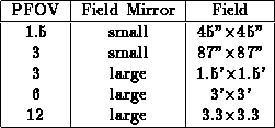
The field mirror acts as a field stop for the light coming from the
telescope. For each channel, there are actually two field mirrors
providing two different fields :  arcmin
 , and
, and
 arcsec
 .
.
With the 1.5 and 3 arcsec PFOV, only the central part of the 3
arcmin diameter unvignetted field of view provided by the
telescope beam is used by ISOCAM; the field of view of the camera
is then limited by the size of the array. When using these lenses in
a raster, the maximum size of the steps should be selected
according to the camera field.
When a 6 arcsec PFOV is selected, there is some vignetting (up to
40 %) in the corners of the  arcmin
 square field of
the array, since the system has been designed to match the 3
arcmin. diameter unvignetted field of view of the telescope.
With 12 arcsec PFOV, the field stop is always the field mirror, and
the outer part of the detector array is not illuminated.

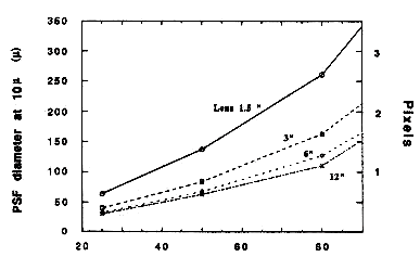
The Point Spread Function (PSF) is a convolution of the diffraction
figure of the 60 cm telescope with the sky sampling of the PFOV.
Figure  shows the PSF diameter as a function of the
encircled energy, for the LW channel at 10
  m, as measured at
instrument level. The PSF is undersampled with the 12 and the 6
arcsec PFOV; it covers about 2 pixels for the 3 arcsec PFOV, and it
is well sampled with the 1.5 arcsec PFOV.The PSF is uniform in the
circular 3 arcmin field of view, but is somewhat degraded in the
corners of the square 3 arcmin.field of view.

Figure: Point Spread Function diameter as a function of the percent
encircled energy at 10  m
m
Due to the off axis field mirror, there is a small field distorsion.
For the 6 arcsec PFOV, an object which would give an image of 32
pixels on the top of the array would give an image of 31 pixels only
in the bottom of the array.
Since it was not possible to have a broad band antireflection
coating on the detector, the detector back reflected light is a
source of stray light. To avoid strong ghost effect, the filters are
titled with respect to the optical axis. Nevertheless, secondary
reflection on the wheels, and on the filter mounts cause residual
ghost images at a level of less than 1%, which changes from one
filter to the other. The worst case is for the 3 arcsec PFOV where
light coming from the whole 3 arcmin field of view falls on gold
connecting strips on the edges of the photosensitive part of the
detectors. To decrease this effect, a smaller field mirror has been
designed which define a field sizeable with the array field of view.
This field mirror has been undersized to take into account
positonning tolerances. In the flight configuration, only 29 x 29
pixels are illuminated with this small field mirror and the 3
arcsec lens. The small field mirror is mandatory when the CVF is
used with the 3 arsec PFOV. With the filters, it is recommended in
case of very strong background.The following table gives the
recommended configurations.
Small field mirror:
1.5 arcsec PFOV with filters or CVF.
3 arcsec PFOV with the CVF.
3 arcsec PFOV with filters and very high background, or presence
of a bright source in the 3 arcmin field of view.
Normal field mirror:
3 arcsec PFOV and normal backgound.
6 arcsec PFOV.
12 arcsec PFOV.
For a full understanding of the observing modes, the parameters to
be specified and the appropriate and most efficient use of the
instrument, some technical information on the arrays is necessary
for the observer to know. These are presented in the following
chapters.


Next: THE SW ARRAY
Up: INSTRUMENT DESCRIPTION
Previous: INSTRUMENT DESCRIPTION
ISOCAM Observer's Manual - V1.0
Tue Oct 31 12:06:23 MET 1995
 ) is based on
an imaging lens which focuses on the detector the image of the sky
provided by the ISO telescope. At the focal plane of the ISO telescope,
a field mirror (also called Fabry mirror) images the telescope pupil on
the camera pupil. The filters and the CVF are located at the camera
pupil position. A pupil stop is placed inside the filter mounts. For
the CVF, an aperture stop is located before the exact pupil location.
The field mirror is also used as a field diaphragm.


 m range, and the long wavelength channel contains 10
filters, and 2 CVF's for the 4.956 to 16.52
  arcmin
 , and
, and
 arcsec
 arcmin
