

Next: Observing Parameters
Up: Oversampled Maps and
Previous: Oversampled Maps and
This observing mode described in detail below is dedicated to perform
scans and maps with PHT-C ( to
to  )
with the best spatial resolution.
Since the scans and maps are obtained from measurements taken at many
different spacecraft pointings not exactly at the same time, care is taken
to optimise the flatfield and to reduce possible striping by
differential and overlapping scans.

The difference between these maps or scans and the normal raster mode is
1) the distance between adjacent beam positions is smaller than the
array size and 2) the array and the scanlines are
aligned. By these means oversampling is obtained
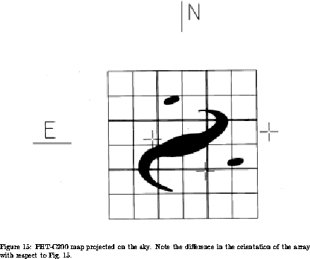
and images overlap without gaps. This is illustrated in Fig. 16.
The complete sequence of celestial positions is measured in one filter
before switching to the next filter and repeating the entire map. Every
such single filter map is embraced by two FCS calibrations.
For a proper reconstruction of the one- or two-dimensional flux distribution
across the source the size of the scan or map should be chosen large enough,
such that background information is contained in the positions at the edges
of the scan or map.
PHT32 performs multi-filter mapping by using either of the PHT-C100 or
the PHT-C200 arrays. The restriction to one detector is necessary because
the different array and pixel sizes require individual mapping
parameters. The map can take the form of a linear scan.
Because of the small pixel number of the PHT-C arrays and the
relatively small field of view (3 arcmin) maps are
obtained by a series of
parallel raster scans with the ISO telescope rather than single pointings
of the arrays. For sampling along the spacecraft Y-axis the
PHT internal focal plane chopper will be used by measuring at positions
intermediate between the regularly spaced spacecraft raster pointings
to increase spatial sampling along the raster legs.
Along the Z-axis the chopper cannot be used, and sampling must be performed
with individual spacecraft pointings. This leads to different sampling step
sizes and, hence, different oversampling factors in Y and Z direction,
respectively (cf. Tab. 11).
By using the chopper for sampling along the Y-axis each celestial
position is observed several times with the same pixel. This way
detector drifts can be monitored for a significantly longer time than
the pure integration time at each chopper position. At the same time
each celestial position is observed with different pixels allowing to
construct a flatfield of the array for each place.
The AOT is designed for
- complete sky coverage
- optimising spatial resolution by allowing for oversampling
- minimising scanning artefacts
The user can specify the orientation of the scan or map on the sky (tolerance
angle). By strictly limiting the orientation range, however, the scheduling
probability of the observation is strongly decreased, since the spacecraft
cannot be rotated arbitrarily around its X-axis (see ISO Observer's Manual).
If no fixed
orientation on the sky is desired, e.g. by using the edge parts of
the map for background determination, the tolerance angle
should be set to 90 degrees, thus minimising scheduling constraints.
The alternative for mapping elongated objects is that the user requests
mapping of a number of smaller square fields, partly overlapping,
by repeating this AOT in a concatenated manner. The
minimum overlap is determined by the demand that full overlap is maintained
when rotating these squares.


Next: Observing Parameters
Up: Oversampled Maps and
Previous: Oversampled Maps and
Tue Dec 6 17:24:45 MET 1994
 to
to  )
with the best spatial resolution.
Since the scans and maps are obtained from measurements taken at many
different spacecraft pointings not exactly at the same time, care is taken
to optimise the flatfield and to reduce possible striping by
differential and overlapping scans.


