
This chapter describes in detail the Top window of PIA shown in Figure 1 and its pull-down items.
Files ManagerThis brings up the PIA Files Control Window (section 3.2.1) for the different files.
Calibration Info
This gives access to all calibration menues and the implementation sequences used to calibrate the PHT instrument and to generate the calibration files CAL-U, CAL-Q and CAL-G for either export to the ISO operational software or for local use with the PHT Interactive Analysis software itself. In the exportable PIA version it should be used to access the calibration numbers used within PIA. The information contained in the Cal G files is accessed to be plotted and edited according to the variables on which depend, present in the corresponding dimensions of the calibration table. The following sub-menus can be reached:
Re-initialize calibrationFile ViewPIA keeps in its memory several calibration tables after program initialization. Whenever calibration files have been changed / replaced it is necessary to re-initialize the calibration data, done with this button. [A change of the path to the CALG files (as described under Customize -> Path below) will follow automatically a question to the user about re-initializing the calibration data.]
Dark Current (obsolete)
This gives access to the old PIA Dark Current CFDP Menu from which the processing of PHT dark current calibration measurements can be performed and the PHT dark current measurement data base can be reached. Warning: this menu access the "old" dark currents (previous to V7.0). The orbital position dependent currents are reached by the menu described below.
Orbital position dependent Dark Currents
This starts a simple menu for accessing the data contained in the Cal G files P#DARKC containing the different PHT detector's dark currents in dependence of orbital position. Plotting and editing of the values is possible.
FCS Calibration Curves
This starts the menu for the calibration of the PHT Fine Calibration Sources (PIA FCS Power Tables CFDP Menu). This menu allows to process FCS calibration measurements per formed with the Calibration Uplink System, transfer the related data into the PIA internal FCS data base and to generate the related CAL-G and CAL-U files. It also allows the user to plot and to edit these tables.
Default Responses (obsolete)
This activates the menu for the calibration of the responsivities of the PHT detectors (PIA Response CFDP Menu). This menu allows response measurements to be processed and the PHT detector default response calibration files to be updated, both for up-link (CAL-U) and downlink (CAL-G) software. These files can also be edited manually. Warning: this menu access the "old" responses (previous to V7.0). The access to the orbital position dependent default responses is described directly below.
Default Responses (orbital position dependent)
This gives access to a simple menu for accessing the data contained in the orbital position dependent responsivity calibration files (P#RESP).
Actual Responses
A menu for accessing the information on the values, which would be used in the case of deriving SPD data using actual responsivities. These values are kept in buffers after calculating them from an FCS calibration measurement. Also the original measurement used is within the accessible information.
Responsivity Check
Menu for processing data to establish the detectors' stability using special designed calibration measurements. Only accessible in the internal version for use of the calibration scientists.
Voltage Linearization
Selection of this sub-menu brings up the menu for the Cold Read-out Electronics (CRE) linearization calibration (PIA CRE linearization CFDP Menu). The generation and editing of the related general calibration files is also possible from this menu.
S-Central Wavelengths
This starts the menu for the calibration of the central wavelengths of the long and short wavelength detectors of the PHT- S spectrometer (PIA S-central wavelength CFDP Menu). The related CAL- G and CAL-U files can be generated from the CUS calibration measurements or can be edited manually.
Vignetting
This starts the menu for the calibration of the vignetting correction (PIA Vignet Table CFDP Menu). The vignetting by the ISO telescope and its baffles imposed on the PHT instrument when using the chopper can be derived from the related CUS measurements. The CAL-G file for this corrections can be generated or edited manually. It is also possible to plot the vignetting for a given PHT filter in order to visualize the impact of this effect on a given astronomical observation.
DIE-Transfer
This starts the menu for the access to the calibration file containing the Digital Interface Electronics (DIE) Transfer Tables (PIA DieTrans CFDP Menu). The menu allows this table to be edited for both DIEs (No.1 and 2) and the related CAL-G file to be up-dated.
Filter2Filter ("Ext. FF")
Menu for accessing the data contained in the Filter-to-filter Cal G files. They were called in the past external flatfield tables, since for the array detectors C100 and C200 they represent for each filter flatfield factors related to the default responsivity.
FCS Illumination Matrix
This starts the menu for the calibration of the inhomogeneous illumination of the PHT-C detectors by the Fine Calibration Sources (PIA FCS illumination Matrix CFDP Menu). This effect is corrected for by a dedicated CAL-G file containing an FCS Illumination Matrix. From this menu the user can edit and plot this file, generate new data from calibration measurements and update the related OLP calibration file for both FCSs (No. 1 and 2).
Point Spread Function
This activates the calibration interface for the point spread functions of the ISOPHOT filters and apertures (PIA PPSF Table CFDP Menu). The menu allows these data to be derived from the related calibration measurements, the point spread functions to be plotted, the CAL-G and CAL-U calibration files to be generated or edited.
NDR General Selection
This starts the menu for the calibration file responsible for steering the selection process of Non-destructive Readouts (NDR) (PIA NDR Default Selection CFDP Menu). The CAL-G file can be edited in order to determine how many NDRs for a give integration ramp are discarded by the PHT OLP pipeline from the processing. This serves to correct for the so called "hook ramps", a bending of the integration ramps, which cannot be corrected by the CRE Linerization.
Colour Correction
Menu for accessing the colour correction factors computed using different models (simple + modified BlackBody models and power law function model).
This item gives access to the PIA File View Window (section 3.2.3). It allows information about several standard ISOPHOT (external fits binary ) files, their availability on the PIA system and their size to be retrieved, without actually reading the files into the buffer. The header can be displayed.
Quit
This leaves the PIA GUI.
Note that from PIA V7.0 onwards leaving PIA is not necessary anymore for beingto able to access the IDL internal PIA buffers (while leaving the GUI causes no problems, since the PIA buffers are intact as long as IDL itself is not left). Now it is possible to manipulate the PIA internal buffers or process the data by IDL commands, while the PIA GUI is fully working.
Buffers ManagerThis brings up the PIA Measurement Buffer Control Panel (section 3.2.2) for accessing the internal buffers.
Astrophysical Work
This starts the PIA Astrophysical Applications Window (section 3.5) which gives access to all AOT specific processing steps beyond SPD level.
Delete Buffers
This frees the memory used by PIA/IDL for internally stored files by deleting a buffer completely. This deletion is necessary on machines which are low on memory or during the processing of very large data files, as the unavailability of memory can cause performance problems. Please note that from the PIA Measurement Buffer Control Panel (section 3.2.2) a partial deletion (selecting measurements for deletion from the buffers) is possible.
The distinction between the various file types allows buffers that are no longer needed to be deleted after a certain processing step has been finished. From this menu point the following data types can be chosen:ERD Buffer
SRD Buffer
SMC Buffer
SCP Buffer
SPD Buffer
AAP Buffer
CS BufferDelete ALL !!
AOT / Batch ProcessingThis calls a sub-menu for the automatic processing of data (as from PHT AOTs). It allows products to be generated which are similar to those of the pipeline, but e.g. using different CAL-G files or different selection settings. All corrections to be applied are choosable and different alternatives for processing are built in.
In addition any data file containing PHT measurements can be automatically processed up to a level comparable to the stages of pipeline products. This is also possible for measurements which were not performed as AOT, e.g obtained using the Calibration Uplink System.
Details about the AOT/Batch processing modes are given in chapter 4, "The automatic modes: AOT/Batch processing".
Concatenate measurements
This option starts a menu originally designed for people working on calibration. Nevertheless it gives the possibility to every user of displaying the signals/signals per chopper plateau of a detector for several measurements vs the relative time to the beginning of the earliest measurement. Data level and detector can be chosen from a widget, given in Fig. 2. Relative times, signals, noises and flags from the chosen measurements are then accessed via a PIA Show Structures menu (section 3.4.4).
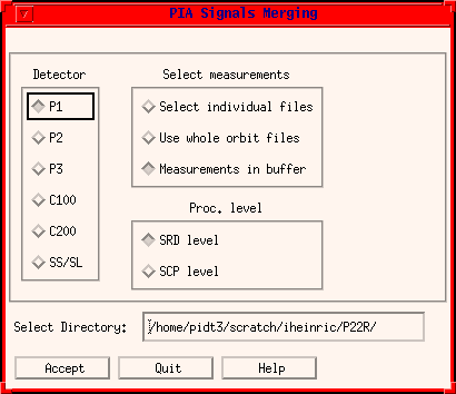
FIGURE 2: The PIA Signals Merging Menu
PrinterThis calls the PIA Printer Definition Window (section 3.4.2).
PIA Color Table
Initializes the colour table settings back to the standard defined by PIA (e.g. after having changed the color table for maps)
Plots in main windows
Set the number N of plots shown in the processing windows (ERD etc.).
PIA paths
The path names as given in Figure 3 can be modified via this context sensitive menu.
External Flatfield
Simple menu for enabling / disabling the use of external flatfield correction for C100/C200 data (enabled by default from V7.0 on).
Error bars in Zoom&Print
Enable/Disable the use of error bars for all PIA_Xplot windows (used for Zoom&Print)
Weighting means
Simple menu for enabling / disabling the use of uncertainties as weights for averaging distributions (enabled by default).
On-target flag value
Enable / disable the use of the on-target flag value associated with a measurement's read-outs. If data taken during a slew has to be used (e.g. serendipity mode, or data between raster points) this flag has to be disabled.
Limits for plots
Put general limits to the number of points in plots (by main windows and Zoom&Print windows separately).
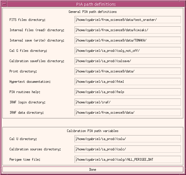
FIGURE 3: The paths definition menu
PIA HomepageThis calls (as background process) the html browser (defined by the w3net alias/logical) pointing to the URL of the official PIA Homepage.
User Manual
This calls the PIA User Manual in the html browser defined by the w3net alias/logical.
This Window
This calls the present page of the PIA User Manual.
A PIA Guided Tour
This calls the page of the Guided Tour (section 2.2) of the PIA User Manual.
PIA Development Team
This calls a WWW page of the PIA Development Team
About PIA
This calls the PIA Acknowlegdement text.
Print User Manual
This calls a menu for sending the whole PIA User Manual (~ 200 pages!) to a printer.
| Date | Author | Description |
|---|---|---|
| 04/07/1995 | Ingolf Heinrichsen (MPIK) /Wai Ming Tai (DIAS) | First Version |
| 25/04/1996 | Martin Haas (MPIA) / Carlos Gabriel (ESA) | General Update |
| 09/04/1997 | Carlos Gabriel (ESA-SAI) | Update |
| 5/06/1997 | Carlos Gabriel (ESA-SAI) | Update (V6.3) |
| 15/10/1997 | Carlos Gabriel (ESA-SAI) | Update (V6.5) |
| 13/02/1998 | Carlos Gabriel (ESA-SAI) | Update (V7.0) |
| 19/08/1999 | Carlos Gabriel (ESA-SAI) | Update (V8.0) |
| 17/03/2000 | Carlos Gabriel (ESA-SAI) | Update (V8.2) |