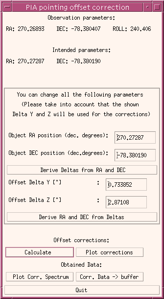
 On the upper part the information on actual pointing observation parameters
are compared with the intended parameters, as entered by the observer in
the proposal. In the rule they should be very close to each other, but
in some special cases they can differ up to several arcseconds.
In the central part of the widget are the editable pointing parameters and the derived offsets in the spacecraft Y- and Z-coordinates. By default the intended coordinates are used to derive the offsets. An observer could wish to enter other coordinates as the intended ones, either because the coordinates were wrong entered in the proposal handling or because the exact position of the object was not well known at the time of proposing the observation.
A change of the RA- and DEC-position of the object should be followed by pressing the button for deriving the offsets, prior to the correction calculation. The opposite is also possible (for calibration purposes), calculating RA- and DEC-positions an object should have according to the edited offsets in Y and Z.
All the action and visualization buttons are placed in the bottom of the widget. Once the calculation of the corrections is performed (just by obtaining the most close position in the footprint matrix for every pixel), the amount of the corrections can be plotted, and the corrected spectrum overplotted over the uncorrected one.
Pressing the button "Corr. Data -> buffer" will create a new measurement within the AAP buffer. The header of the measurement contains several keywords giving the RA and DEC coordinates assumed for the correction as well as the derived offsets.
Fig. 1: The widget for the PHT-S pointing offset correction.