


Next: 7. SWS Calibration
Up: 6. The RSRF and
Previous: 6.6 Spurious Narrow Spectral
RSRF curves for all bands are plotted in this section. Note that the graphs
are not noisy, but are affected by high frequency fringes.
Figure 6.6:
The RSRF for band 1A based on a measurement of HR7001 (black)
versus the RSRF as measured in the lab (grey). The fringes in the in-orbit-RSRF
are real.
 |
Figure 6.7:
The RSRF for band 1A based on a measurement of HR7001
(black) and the lab RSRF corrected to the overall shape of the in-orbit RSRF.
Note that not every feature that was seen in the lab has been seen in orbit.
Especially the differences in the 2.35 - 2.40  region are relatively large.
Similar features seen in SWS spectra might be not real.
region are relatively large.
Similar features seen in SWS spectra might be not real.
 |
Figure 6.8:
The RSRF for band 1b based on a measurement of HR7001 versus
the lab RSRF (grey). The fringes in the in-orbit-RSRF are real.
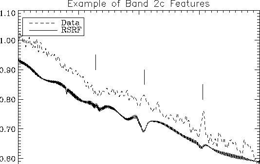 |
Figure 6.9:
The RSRF for band 1d based on a measurement of HR7001 versus
the lab RSRF (grey). The fringes in the in-orbit-RSRF are real.
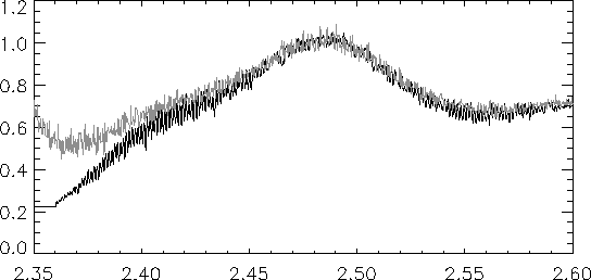 |
Figure 6.10:
The RSRF for band 1e based on a measurement of HR7001 versus
the lab RSRF (grey). The fringes in the in-orbit-RSRF are real.
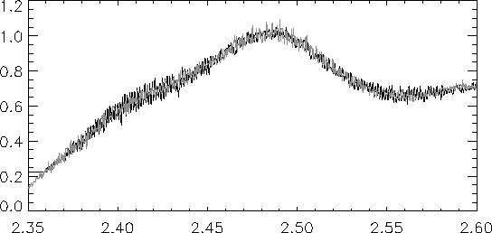 |
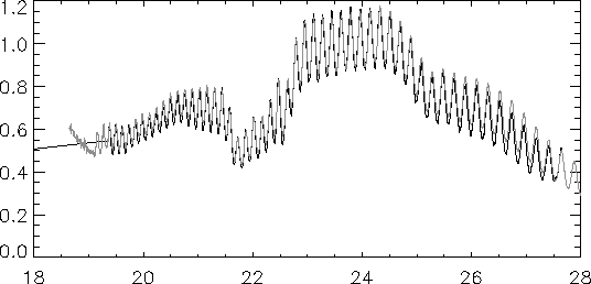
Figure 6.11:
The RSRF for band 2a based on a measurement of HR7001 versus
the lab RSRF (grey). The fringes in the in-orbit-RSRF are real.
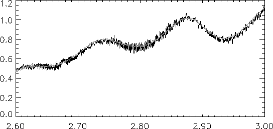 |
Figure 6.12:
The RSRF for band 2A based on a measurement of HR7001
(black) and the lab RSRF corrected to the overall shape of the in-orbit RSRF.
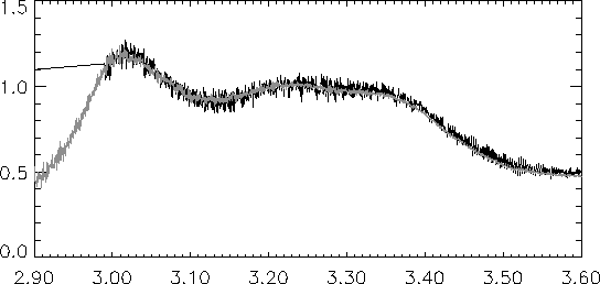 |
Figure 6.13:
The RSRF for band 2b based on a measurement of HR7001 versus
the lab RSRF (grey). Also in this band the lab measurements seem to show
leakage. Attempts to correct the overall shape did not survive cross-checks
with other calibration sources.
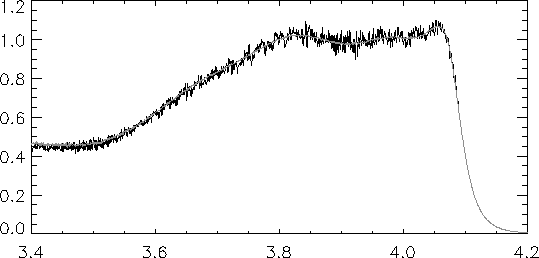 |
Figure 6.14:
The RSRF for band 2c based on an AOT 1 speed 4 measurement of
HR5340 (black) versus the lab RSRF (grey). The small features between 7 and 8
microns and around 10 microns can introduce misleading features after
incorrect dark. The increase in response beyond 12 microns has been seen in
other sources.
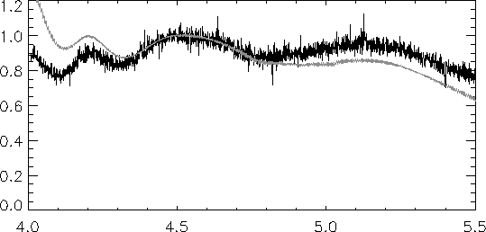 |
Figure 6.15:
The RSRF for band 3a based on a measurement of NML-CYG
versus the lab RSRF (grey). There is a good match, even at the fringe level.
The fringes are a little ``sharper'' in the in-orbit RSRF because of the
limited resolution of the lab measurements. Wrong dark subtraction will
produce many spurious features.
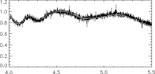 |
Figure 6.16:
The RSRF for band 3c based on a measurement of NML-CYG versus the lab
RSRF (grey). There is a good match, even at the fringe level. The fringes are
a little 'sharper' in the in-orbit RSRF because of the limited resolution
of the lab measurements. Wrong dark subtraction will produce many spurious
features.
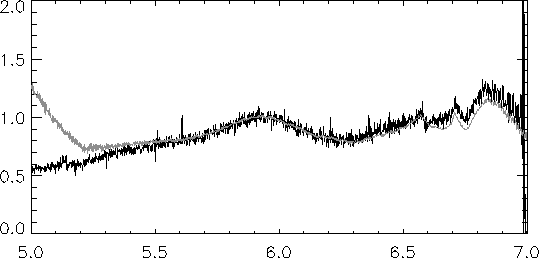 |
Figure 6.17:
The RSRF for band 3d based on a measurement of NML-CYG versus the lab
RSRF (grey). There is a good match, even at the fringe level. The fringes are
a little 'sharper' in the in-orbit RSRF because of the limited resolution
of the lab measurements. Wrong dark subtraction will produce many spurious
features.
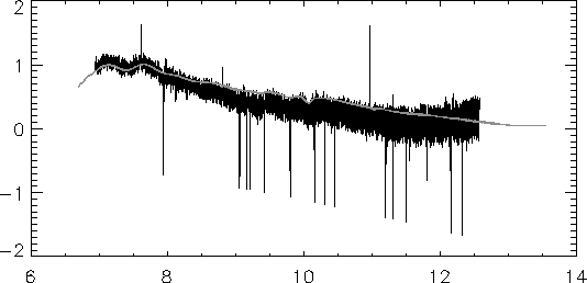 |
Figure 6.18:
The RSRF for band 3e based on a measurement of NML-CYG versus the lab
RSRF (grey). There is a good match, even at the fringe level. Wrong dark
subtraction will produce many spurious features.
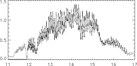 |
Figure 6.19:
The RSRF for band 4 based on a measurement of NML-CYG versus the lab
RSRF (grey). Since the model of NML-CYG is only accurate to 30%, it is not
clear if the in-orbit RSRF is actually different from the lab RSRF.
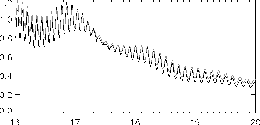 |
Figure 6.20:
The RSRF for band 4 based on an AOT 1 speed 4 measurement of ETA-CAR
versus the lab RSRF (grey).
 |
Next: 7. SWS Calibration
Up: 6. The RSRF and
Previous: 6.6 Spurious Narrow Spectral
SWS Instrument & Data Manual, Issue 1.0, SAI/98-095/Dc