

Next: 4.5 Flat-Fields
Up: 4. Calibration and Performance
Previous: 4.3 Glitches
Subsections
4.4 Transients
The occurrence of transients in responsivity after changes in the
incident photon flux is a well known problem of extrinsic infrared
photodetectors (see Fouks 1992, [31];
Coulais et al. 2000, [23] and
references therein).
In general, the transient response of such detectors cannot be
easily described because the responses are non-linear and
non-symmetrical. The transient not only strongly depends on the
detector material and on the level of the incident flux, but also on the
prehistory on the detector illumination and, for matrix arrays, on
the signal gradient between adjacent pixels.
Both SW and LW detectors of CAM present strong responsive transient
effects. Stabilisation after changes of incident flux was the main
problem encountered with these arrays.
After a change of incoming flux, several tens, hundreds or
even thousands of readouts may be necessary to reach stabilisation at
the new flux level.
Because of this behaviour it was recommended for each measurement
to let the signal stabilise for a number of readouts ( ),
before recording the science exposures (
 ). It was
however, for most observations, impossible to reach a fully
stabilised signal, so that methods had to be developed to correct
the data for the transient behaviour. These methods will be discussed
in the following subsections.
The worst cases were the
following: a) switching to illumination after having the detector in
the dark (the dark position of the entrance wheel); or b) after a
saturating flux.
The first problem could be reduced for the LW array by keeping
always light on the array (e.g. by configuring the instrument to the
ISOCAM parallel mode (Section 3.6) when ISOCAM was
not used in prime mode) and executing the observations
in order of decreasing flux. Dark calibrations were placed at
the end of the science observations, or in those revolutions
with no ISOCAM science activity in prime mode. An extensive
description of the responsive transients after flux steps for the two
detector arrays will be described in the following subsections.
The responsive transient effect is one of the most important
sources of systematic error in ISOCAM data. Therefore, it is
mandatory to understand something of the nature of these transient
effects and to apply transient correction methods.
4.4.1 SW transients
For SW, which accounted for only 5% of all CAM observations, a
detailed physical model of the transient behaviour is
lacking.
Tiphène et al. 2000, [60] claim that the
evolution of the responsivity with accumulated signal is likely to be
related to surface traps in the semi-conductor. Those traps have to
be filled first with photon-generated charges before the well begins
to accumulate signal.
Starting from the observation that the lower the signal, the longer
the corresponding time constant, Tiphène et al. 2000,
[60] developed a model that reproduces quite well
the transient behaviour,
using only a small set of parameters. The model provides the
asymptotic value of the stabilised signal. However, because of the limited
number of test cases available it is difficult to judge whether the
method is generally applicable to the full range of SW data.
4.4.2 LW transients
The transient behaviour of the LW channel has two main components:
a short term drift with an amplitude of
typically 40% of the total stabilised flux step, and a long term
drift or transient (LTT in the following) with a typical amplitude of about
5% of the total flux step (Abergel et al. 1999,
[1]). The short term response at a given time strongly
depends on the illumination history of the detector, and
also on the spatial structure of the sky field viewed. The LTT can affect
the data for hours, but does not always occur. These effects
will be described in the following subsections.
4.4.2.1 LW transients under uniform illumination
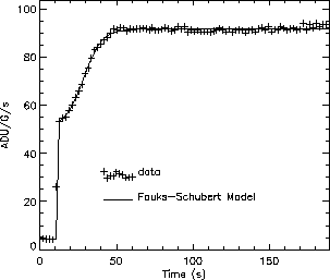
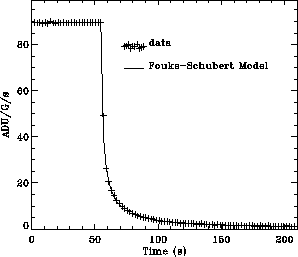
The short term transient (see Figure 4.7)
of the LW channel has the following components:
(1) an initial jump of about 60% of the total signal step and
(2) a signal drift behaviour which depends on the flux history,
on the amplitude of the current step,
on the pixel position on the detector matrix and on the local spatial
gradient of the illumination (Abergel et al. 1999,
[1]; Coulais & Abergel 2000,
[21]).
Upward and downward steps are not symmetrical.
Figure 4.7:
Upward and downward steps of flux
(Up : in-flight data, TDT 12900101, down : ground based test).
These examples show that the transient response is clearly
non-symmetrical.
|
|
It has been shown in Coulais & Abergel 2000, [21]
that under
quasi-uniform illumination of the detector array the short term
transient response of individual pixels can be described by an
analytical model, with an accuracy of around 1% per readout
(for all pixels except those near the edges of the array).
This Fouks-Schubert model (FS model in the following) was initially
developed for ISOPHOT Si:Ga detectors
(Schubert et al. 1994, [53]; Fouks & Schubert 1995,
[32]).
This is not an empirical model, but a true physical model, based upon
a detailed knowledge of the detector construction and properties.
It is a `1-dimensional model', in the sense that:
(1) the pixel surface is assumed to be uniformly illuminated; and
(2) one pixel does not interact with other pixels
(the cross-talk between adjacent pixels compensates each other).
The following equation describes the response for an
instantaneous flux step at time  , from the constant
level
  to the constant level
  :
:
 |
|
|
(4.1) |
 is the stabilised photocurrent measured at time
 .
It is also directly related to the observed flux, since a linear
relationship is assumed between the flux and the photocurrent after
stabilisation. The parameter
  characterises the instantaneous
jump just after the flux change. The theory gives a simple
relationship between the time constant
  and
and  over
several orders of magnitude:
 . Yet, the time constant is
  .
This non-linear and non-symmetrical FS model describes well
the detector behaviour in response to both upward and downward flux
steps, for a large range of flux changes.
The description of the physics of the model, and the relevant
hypotheses and simplifications are detailed in
Fouks & Schubert 1995, [32] and the application
to the ISOCAM LW
detector is described in Coulais & Abergel 2000, [21].
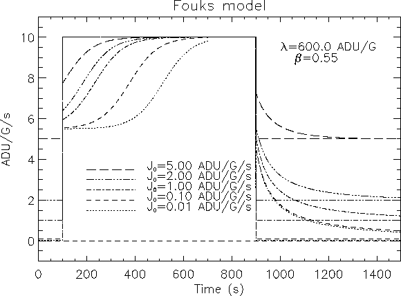
Characteristic simulated outputs of the FS model are shown in
Figure 4.8.
The transient effect described by the FS model is sometimes called
the `short term' transient in contrast to the long term drift
(LTT). But at low input flux levels this short term transient
can be very long.
(e.g. CVF observations with signals exceeding the dark level by only
5 ADU/s).
The FS model is fully characterised by two parameters for each pixel:
i) the amplitude of the instantaneous jump
  , and
ii) a constant
  in the exponential term.
No significant changes of these parameters were observed during the
whole lifetime of ISO, so that only one 32
 32 map for
each parameter is provided (CCGLWTRANS, Section 6.1.10).
The FS model is used in the transient correction applied in the ISOCAM
Auto Analysis (Section 7.2.5).
The application of this transient correction method to ISOCAM data
(including a list of frequently asked questions about the FS model)
is discussed in Coulais & Abergel 2002, [22].
Further details can be found in Coulais & Abergel 2000,
[21] and Coulais et al. 2000,
[23].
Figure 4.8:
Simulated transient responses in the Fouks-Schubert model
for upward and downward flux steps.
Upward steps of flux from a constant level  to a constant level
  occur at time
  s and downward
steps from
  to
to  occur at
  s. We have taken:
 = 0.01, 0.1, 1.0, 2.0 and 5.0 ADU/G/s, and
  = 10
ADU/G/s.
For all these simulations, the values of the parameters
 and
and  are constant.
We see that this model is very sensitive to the initial level
 for the upward steps :
curves from 0.01, 0.1 and 1.0 ADU/G/s are very different.
When the dark level is poorly estimated, such non-linear effect can
allow us to estimate the value of
  .
.
|
|
4.4.2.2 LW transients for point sources
In the LW array, the pixels are defined by the electric field
applied between the upper electrode and the bottom 32 32 contacts
(Vigroux et al. 1993, [63]).
As a consequence of this electrical design of
the array, adjacent pixels are always affected by cross-talk.
Under uniform illumination, the instances of cross-talk compensate
for each other. But this is not the case when the input sky exhibits
strong fluctuations with angular scales around the pixel size
(e.g. point sources with gradients between pixels typically higher
than 20 ADU/s). The 1-D FS model, described in
Section 4.4.2, fails for such point sources,
and 3-D models are required.
A new 3-D physical model has recently been developed by
Fouks & Coulais 2002, [33].
In order to test this model and compare
it with the observed
transient responses for CAM point sources, a simplified 2-D
model, using symmetry properties of the detector array and of the
point sources was derived. Under uniform illumination, this 2-D model
was carefully compared with the 1-D model and both were found to
give the same transients.
Without any modification, using the same (
 ,
,  )
parameters as for
a uniform illumination, the new model immediately gave also the correct
shape for
the transients of the sharpest point sources which are very different from
the transient responses predicted by the 1-D model (see
Figure 4.9).
Figure 4.9:
Data taken from the TDT 35600501 (filter LW5, lens
3
 ). Brightest pixel: (10,15). Left panel: the data, and
overplotted the 1-D Fouks-Schubert model to be used for uniform
illumination
case. For all the curves, the black lines are for the brigthes pixels,
the blue line is the mean value of the
  pixels,
the red lines are the 4 closest pixel to the brightest,
and the green lines represent the 4 diagonal pixels.
Right panel: the data, and overplotted with the new model for point
source
transients. Since in this configuration a narrow PSF is obtained, a good
agreement between the data and the new model is expected. In both cases the
same
  and
and  values are used. The unknown parameters are J
 and
J
and
J .
.
![\begin{picture}(15.,8.)
%
%
\put(0.0,0.0){\includegraphics* [200,85][430,300,...
...ox (8.05,8.05){}}
\put(8.05,0.){\framebox (8.05,8.05){}}
%
\par\end{picture}](img123.gif) |
The new model works best for narrow
PSFs. The model can still be improved for configurations in which the
PSF is wide, for instance in the case
of 1.5
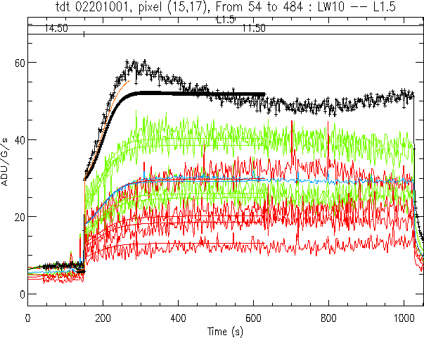
 and the long wavelength filters. An example of the
present status of the correction for a wide PSF, is given in
Figure 4.10. The transient response of the mean
value
of the
  pixels centered on the brightest pixel is accurate up to
the percent-level. For the individual pixels the accuracy achieved is a few
percent.
The new 3-D model is not used in the CAM OLP but is made available together
with further information on request either by directly contacting Alain
Coulais (currently at LERMA, Observatoire de Paris-Meudon) or through
the ISO Helpdesk ( helpdesk@iso.vilspa.esa.es).
Figure 4.10:
Data taken from the TDT 02201001
(filter LW10, lens 1.5
 ). The different colours represent
data from different pixels as explained in
Figure 4.9.
In this configuration, the point source has one of the largest possible
FWHM of the PSF. For such a configuration the 2-D model gives a worse
agreement between the data and the model on a pixel per pixel base than
is found for smaller PSFs as in Figure 4.9. A
better agreement is obtained for the
  mean value.
The brown curve shows a second order correction term (which may be an
improvement of the method, but which has not been extensively tested yet).
It should be noted that these data are difficult to process because
the illumination before the observation of the source is not uniform.
As usual with such non-linear models, the results are very sensitive
to the initial level, and, in this case, to its profile. Here,
only a mean value was used, which may produce some error for the brightest
pixel.
|
|
4.4.2.3 LW long term transients
The LW array is also affected by long term transients (LTT).
After an upward flux step, a drift becomes apparent generally
after the stabilisation of the short term transient,
while all the instrument parameters and the input flux are constant.
This drift is characterised by a long term variation of the measured
signal by a few percent (2 to 5%, see Figure 4.11).
No LTT has been observed for downward steps.
The LTT has never been modelled and it is not clear whether or not it
may be stochastic.
From ground based data, it seems that:
- This drift always exists for steps higher than hundreds of ADUs;
- The lower the initial level, the higher the drift amplitude.
A similar drift effect was predicted by
Vinokurov & Fouks 1991, [62]. Their
physical model has been compared to several ground based data sets
(Coulais et al. 2001, [24]).
However, the parameters of the model have to be separately adjusted for
each data set, making it unsuitable for general application. The main
technical problem comes from the large uncertainty in determining the
absolute dark level.
Figure 4.11:
This CAM LW in-flight observation starts just after
the switch-on at the begin of a revolution.
We clearly see the two components of the transient response:
the short term transient from time  0 s to
  50 s,
which is the transient response described by the
Fouks-Schubert model and, from
  100 s to the end, the response
change due to the long term drift (LTT).
In this observation, the LTT amplitude is
  7%
which is especially strong for in-flight data.
|
|
The characterisation of in-flight LTT is even more complicated,
and, up to now, no reproducible effects have been found.
At the present time, since physical models cannot be used
to describe the data affected by LTT, empirical dedicated
processing methods have been developed.
Two approaches exist for the extraction of reliable information
from raster observations affected by LTT.
For the case of faint point sources, as in cosmological surveys,
source extraction methods are discussed in
Starck et al. 1999b, [59]
and Désert et al. 1999, [29].
For raster maps with low contrast large-scale structure
(as in the case of diffuse interstellar clouds)
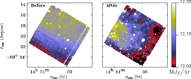
an LTT correction method is now available in CIA.
This method was developed by Miville-Deschênes et al. 2000,
[41] and is
based on the use of the spatial redundancy of raster observations
to estimate and to correct for the LTT
(see Figure 4.12).
A further description of this method
can be found in Appendix F.
Figure 4.12:
When the contrast of the observed object is very low,
and when the observations suffer from the Long Term Transient effect,
it is important to use a correction method based on the spatial
redundancy of raster observations.
In the present case, the structure of a low contrast
diffuse interstellar cloud is recovered (see Miville-Deschênes
et al. 2000, [41] for more details).
|
|


Next: 4.5 Flat-Fields
Up: 4. Calibration and Performance
Previous: 4.3 Glitches
ISO Handbook Volume II (CAM), Version 2.0, SAI/1999-057/Dc


![\begin{picture}(15.,8.)
%
%
\put(0.0,0.0){\includegraphics* [200,85][430,300,...
...ox (8.05,8.05){}}
\put(8.05,0.){\framebox (8.05,8.05){}}
%
\par\end{picture}](img123.gif)
![\resizebox {13cm}{!}{
\includegraphics*[5,5][480,330]{fig1_transient_long.eps}}](img128.gif)
